PFAS-free POF and vibration-enhancing structures for social presence through immersive, emotional and vivid experiences of closeness at a distance
Raw materials Fibres Sustainability Smart Textiles
Abstract
The three-year project ‘SPIELEND – Social Presence through Immersive, Emotional and Lively Experiences of Closeness at a Distance’, funded by the BMFTR, addresses the question of how technology-assisted games should be designed to convey a feeling of social closeness to participants even across distances. This explicitly includes the representation of the other person or fellow players. In order to measure the resulting closeness, the corresponding evaluation options are derived from psychological and cognitive science research within the framework of the project. As part of the project, various digital augmented reality games are being designed, implemented and tested. In order to enable an immersive and emotional experience and to create a heightened sense of social presence, the augmented reality games are being developed with the inclusion of smart, functional textiles.
Report
1. Abstract
See „abstract for TEXCAMPUS“
2. Introduction
Our society is undergoing change: education, study and work, but also the shortage of housing in urban centres, are placing increasing demands on citizens' mobility [1]. At the same time, travel is proving to be an unsustainable solution in terms of its ecological and economic consequences [2]. Social distancing during the COVID-19 pandemic exacerbated the separation of families, friends, club members and church communities. According to [3], 69% of respondents did not have any private meetings during the coronavirus measures in 2020. At the same time, the pandemic accelerated the digitalisation of social interaction. One in two people aged 16-29 used video calls to communicate with family and friends [4]. While these developments appear welcome in terms of resource efficiency, there are also negative effects of digital communication that lack social proximity: video conferences cannot replace real meetings; there is a lack of spontaneity, non-verbal communication, playfulness and emotionality. So-called ‘Zoom fatigue’ is becoming widespread [5]; people are rarely willing to hold private video conferences with family and friends.
The aim of the three-year BMFTR project SPIELEND is to develop a system that enables physical and emotional immersion in the context of playful interaction at a distance in order to intensify a feeling of closeness. Well-known game concepts are used, further developed and expanded to include sensory qualities, in particular through polymer optical fibres (POF) and 4D textiles. This makes it possible to support loved ones who suffer from the social side effects of physical separation. Smart textiles are being used in particular to enhance sensory qualities. The study focuses on the factors influencing social presence, such as the representation of fellow players, multimodal stimulation and game elements, including joint activities.
3. Materials and methods
Two types of smart textiles are used for physical distance interaction: textile emitters in the form of polymer optical fibres (POF) and 4D textiles.
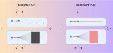
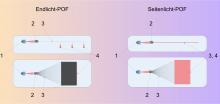
POFs are designed either as end-light fibres or side-light fibres. End-light fibres conduct the coupled light from the end of the fibre closest to the light source to the end furthest from the light source. Side-light fibres, on the other hand, also emit light across the entire surface of the POF. End-lighting POF can therefore be used for spot lighting and, when integrated into a textile structure, for line lighting. Side-lighting POF can be used for line lighting and, when integrated into a textile structure, for area lighting (see Fig. 1). All commercial plastic light-conducting fibres consist of two polymer materials. One is polymethyl methacrylate (PMMA) in the fibre core. The other is a fluoropolymer in the fibre cladding. Commercial POF is therefore contaminated with PFAS. As part of the project, possible alternative cladding materials are being investigated and PFAS-free POF is being produced using the bicomponent melt spinning process.
see Fig. 1 Illustration of various application options for end-lighting POF and side-lighting POF
Common materials for textile actuators are PLA (polylactide) and TPU (thermoplastic polyurethane). Critical factors for textile actuators are the adhesion properties and ensuring the flexibility of the textile. For the vibration propagation structure, the polymers TPU and PLA were considered, as well as the two textiles Eurojersey and Buttinette.
4. Results
Through theoretical material screening based on optical, thermal and economic evaluation criteria, the following polymers were identified as possible alternatives to the fluorinated material currently in use: polymethyl pentene (PMP) and polylactic acid (PLA) – with the former appearing more promising in preliminary practical tests. Through material screening based on optical, rheological and thermal evaluation criteria, three types of polymethylpentene (PMP grades) were selected for testing: TPX MX002, TPX DX820 and TPX RT18 – all from Mitsui Chemicals, Inc., Tokyo (Japan) (see Fig. 2). Through multiple iterative experimental analyses using bicomponent melt spinning tests and subsequent geometric, mechanical and optical evaluation methods, insights and improvements in the production of PFAS-free materials were achieved. PFAS-free POF with a roundness of over 99% was produced using the three PMP grades and PMMA 7N from Röhm GmbH, Darmstadt (Germany). The fineness-related strengths achieved are comparable to commercial POF. Using DX820 as the sheath material, a maximum sheath extruder temperature of 255 °C and a nozzle hole capillary diameter of 3.5 mm, PFAS-free POF (diameter 500 µm) with the lowest attenuation was produced.
see Fig. 2 Used Granulates
For the application of textile actuators on textiles, it was found that the common materials PLA and TPU can be printed using fused deposition modelling (FDM). TPU showed superior adhesion compared to PLA and was selected as a suitable material for smart textiles due to its better adhesion properties and flexibility. To identify suitable material combinations for the vibration propagation structure, the adhesion at the interface between the polymers and the textiles was systematically analysed. The results show that PLA has the best adhesion properties on Buttinette textiles, while TPU shows improved adhesion on Eurojersey textiles. These material combinations were determined to be optimal for the further development of the vibration propagation structure. As part of the investigation of textile actuators, TPU and Eurojersey were identified as a suitable material combination. The selection was based on the soft texture of TPU and its improved adhesion to Eurojersey. These properties enable optimal interaction with the textile structure and are particularly advantageous for the implementation of tactile feedback (see Fig. 3).
see Fig. 3: Vibration propagation structure
5. Summary
The SPIELEND project represents an innovative approach on two levels to expand the experience of digital games for remote interaction and thus make them more accessible (see Fig. 4). Vibration propagation structures on textiles are being explored to make the gaming experience physically tangible. This allows feedback to be passed on directly to the player. Thermoplastic polyurethane on a Eurojersey textile was found to be the best material combination. On the other hand, the use of light-conducting fibres made of plastic (polymer optical fibre, POF) makes it possible to enhance the gaming experience with realistic visual stimuli. For this purpose, PFAS-free POF was designed theoretically and manufactured practically using the bicomponent melt spinning process, which means that it is not contaminated with fluorinated substances.
see Fig. 4: Smart vest with POF light strip, vibration amplification structure and control via RoboHeart from project partner Augmented Robotics
6. Acknowledgement
We would like to thank the Federal Ministry of Research, Technology and Space (BMFTR) for funding the SPIELEND research project (FKZ: 16SV9098). We would also like to thank everyone involved in this project for their contributions and commitment.
7. Bibliography
[1] Deutschland Bundeszentrale für Politische Bildung, Datenreport 2021 ein Sozialbericht für die Bundesrepublik Deutschland. 2021.
[2] Europäische Kommission und Generaldirektion Mobilität und Verkehr, „EU transport in figures: statistical pocketbook 2021“. Publications Office, 2021. Accessed: 11. February 2022. [Online]. Available at: https://data.europa.eu/doi/10.2832/733836
[3] „Statista: Häufigkeit von privaten Treffen pro Woche vor und während der Corona-Maßnahmen 2020“, 2020. https://bit.ly/3BlCgOj. Accessed: 11. February 2022.
[4] „Statista: Umfrage zu erhöhter Nutzung von Videoanrufen während der Corona-Krise nach Alter 2020“. https://bit.ly/3HOOG3n. Accessed: 11. February 2022.
[5] J. N. Bailenson, „Nonverbal Overload: A Theoretical Argument for the Causes of Zoom Fatigue“, Technol. Mind Behav., Bd. 2, Nr. 1, Feb. 2021, doi: 10.1037/tmb0000030.
More entries from ITA Institut für Textiltechnik der RWTH Aachen University


![Figure 5: Response for the sensor filament PP/TPU (ΔR/R [-] left and ΔR [Ω] right)](/sites/default/files/styles/thumbnail/public/2023-08/fig5.jpg?itok=pUzdudyi)

![Figure 7: ΔR [Ω] response for the sensor filament PP/TPU without the outliers 4 and 5](/sites/default/files/styles/thumbnail/public/2023-08/fig7.jpg?itok=9319hryM)


